Microcontroller Projects
After learning C++ through MATLAB, I was introduced to the Arduino ecosystem and its open-source philosophy. Arduino’s hands-on learning environment allowed me to quickly build a foundation in electronic wiring and microcontroller programming, sparking a series of increasingly complex projects that continue today.
Another early Arduino project was inspired by the arcade-style game Geometry Dash. In the game, the player controls various shapes—such as a cube, ball, or UFO—using a single-touch input to navigate through timed obstacles. After repeatedly encountering the limits of human reaction time, I realized that Arduino timing resolution, accurate to milliseconds, far exceeds human precision. With proper configuration, an Arduino could theoretically control the game input and complete levels with near-perfect consistency.
Hardware
The hardware design was intentionally simple. Since the game relies on one-touch input, the system required a mechanical “tap” mechanism. After multiple design iterations, the most reliable solution was a touchscreen stylus mounted to a servo motor. The Arduino rotated the servo approximately 20 degrees to tap the screen, then returned it to its home position, effectively simulating a player input.
Software
The software initially used an open-loop control approach, commanding the servo based on predetermined timing sequences. While this method could solve portions of a level, it was time-intensive to tune and inconsistent across maps. The system was later upgraded to a closed-loop learning approach. By incorporating a microphone to detect in-game collision sound effects, the Arduino could identify failure events and adjust its timing parameters accordingly. This allowed the system to iteratively refine its control strategy and improve performance over successive attempts.

Servo Diagram
This diagram shows how the Arduino communicates with the servo.
Note: Servos have integrated gears and a shaft that can be precisely controlled. Standard servos allow the shaft to be positioned at various angles, usually between 0 and 180 degrees.

Electrical Schematic
The servo motors have three wires: power, ground, and signal (red, black and yellow respectfully). The power was connected to the 5V pin on the Arduino board. The ground wire is was connected to a ground pin on the board. The signal pin is was connected to pin 9 on the board.
Arduino Visualizations
Live music was not something I initially associated with my engineering projects. However, after being exposed to the creativity and technical complexity behind live visualizations, I took the opportunity to design a system capable of controlling interactive spotlights, fog machines, and lasers.
Arduino was a natural choice for the control platform. I initially implemented an open-loop system using simple commands such as digitalWrite() and timed delays to control voltage output to the visualization components. While effective in a static environment, this approach proved impractical for live performances, where bands rarely maintain a perfectly consistent tempo.
To address this limitation, I redesigned the system to use operator-initiated control. The Arduino was programmed with multiple lighting and effects sequences that could be triggered in real time via pushbutton inputs. This hybrid approach preserved the reliability of microcontroller control while allowing human timing to drive the performance, resulting in a system that was both responsive and adaptable to live music.


Hardware:
I could have easily controlled the lighting sequences for LEDs the tricky part comes when we need to control the sequences for floodlights (120V). The Arduino pin output is 3.2V, so I needed a solid-state relay that I could switch on and off with the Arduino.
The solid-state relays allowed me to control the power going to any 120V device. With this box, I initiate sequences of lights, laser and fog machines via pushbuttons wired to the Arduino. Essentially, anything that plugs into a household outlet could be controlled.


The Weightless Bulb
I was inspired to build this project through my fascination with minimalism. I always dreamed of a household with no ugly exposed wires, adaptors or plugs. Upon studying transformers I discovered the wonders of electromagnetic induction. By using Faraday's law of induction we can achieve wireless power. I then realized since I no longer have wires tying me down, why not break the bounds of earth's gravity and create a floating wireless light.
This system uses two separate circuits in order to accomplish this task.
The system archives levitation through giving pulses of power to an electromagnet. The distance from the magnet to the electro-magnet is measured via a linear hall effect sensor. The sensor was placed in between the magnet and electro-magnet. The sensor would then increase or decrease the voltage going to the electromagnet based on demand. The system works in order to keep the object in stable equilibrium.
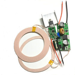
The second circuit is what transfers power wirelessly to the LED light. This is done by using a primary and secondary coil in order to generate electromagnetic induction. The induction transfers power through a magnetic field from the coil to the coil. This is very similar to how a transformer works.